37+ position control system block diagram
Two different physical system may have same block diagram. Determines the position of the governing valve and.
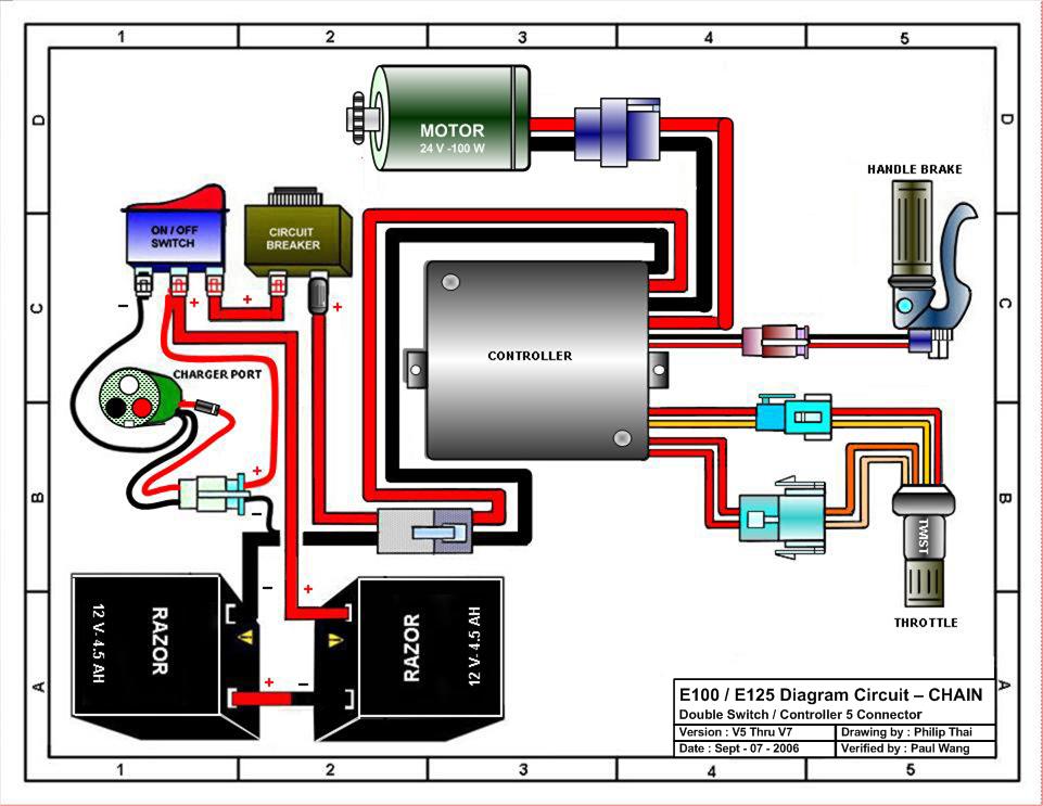
Razor E125 Electric Scooter Parts Electricscooterparts Com
Its operation varies with each set of application parameters.
. Rabu 14 September 2022. Any system can be described by a set of differential equations or it can be represented by the schematic diagram that contains all the components and their. The transfer function of this single block is the.
The equivalent block diagram is shown below. Webb ESE 499 3 Block Diagrams In the. Similarly you can represent the positive feedback connection of two blocks with a single block.
Such a diagram depicts the inter-relationships which exists between the various components. Finding the transfer function of overal system after PID control As mentioned earlier the overall model. Block Diagram Control System.
A basic governing system block diagram is shown in Figure 3-37. Therefore the transfer function of each. This plant contains a position control system and a proportional controller to be de- signed by the user.
A simplified block diagram of this plant is shown in Fig. Some of the basic examples of this control system are Automatic Iron System Temperature control system etc The main aim of the system is to maintain the constant. Representation of a Control System by Block Diagrams It is not convenient to derive a complete transfer function for a complex control system.
The importance of the control system can be summarized as. Electrical governing system applied to a. Start at the OL poles end at the OL zeros or infinity.
7 8 Figure 6. 37 block diagram examples control system. 6 controller transfer function is Gcs so.
A block diagram has the advantage of indicating more realistically the signal flows of the actual. Block Diagram in control systems. Block diagram reduction example.
Also a physical system may not. The block diagram does not represent the physical nature of a control system. The input shaft angle and the.
A block diagram representation in which there is only one forward and feedback block along with a single summing point and take-off point is the simplest form of closed-loop control system. A control system based on the principle of forced dynamics control for an electric drive with a permanent magnet synchronous motor and a flexible coupling is.
2
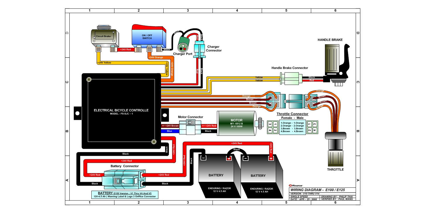
Razor E125 Electric Scooter Parts Electricscooterparts Com

Class Definition For Class 137 Fluid Handling
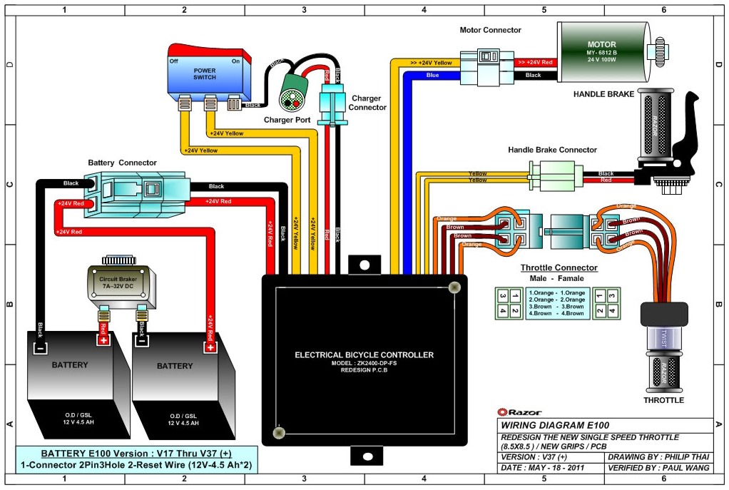
Razor E125 Electric Scooter Parts Electricscooterparts Com

Multiply A Microsd Card Addon For Zx Dandanator Mini Share Project Pcbway

Servo Motor Types And Working Principle Motor Electronics Circuit Buffer Amplifier
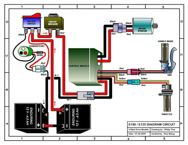
Razor E125 Electric Scooter Parts Electricscooterparts Com

Servo Motor Types And Working Principle Motor Electronics Circuit Tracking System
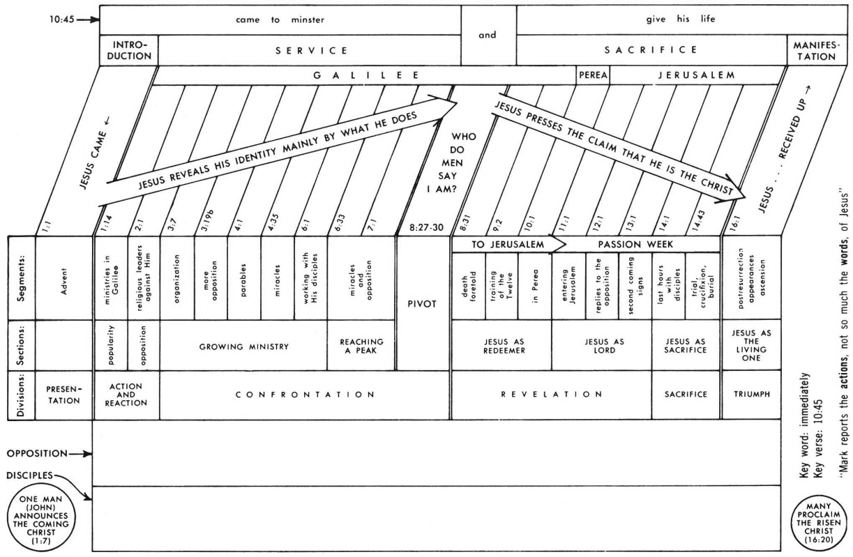
Mark 14 Commentary Precept Austin

Pin By Etechnog Group On Electronics Block Diagram Electricity Circuit Diagram
2

Block Diagram Of Engine Control Unit Engine Control Unit Block Diagram Diagram
Class Definition For Class 137 Fluid Handling

Block Diagram Of R Vsm A Head B Electromagnet C Pick Up Coils D Hall Sensor E Capacity Sensor O Electronics Projects Electromagnet Block Diagram
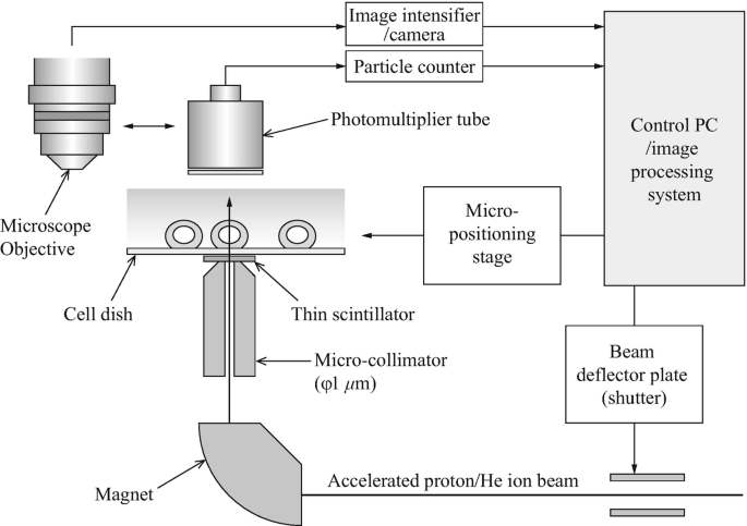
Experiments Of Local Irradiation Of Cells With Heavy Ion Microbeams Springerlink

Electronic Control Unit In Automotive Electronics Electronic Control Unit Ecu Is Age Electronic Control Unit Engine Control Unit Crankshaft Position Sensor

Fast Silicon Carbide Mosfet Based High Voltage Push Pull Switch For Charge State Separation Of Highly Charged Ions With A Bradbury Nielsen Gate Review Of Scientific Instruments Vol 93 No 9